Steam Quality Test Points
In order to test the steam quality specific test points on the steam line are required.
Fig 1 illustrates the location of the three test points on the steam supply pipe just prior to the sterilizer. This test point is usually installed between the steam main supply isolating valve and the sterilizer.
An assumption made, but not stated by HTM 2010 is that the test point will be fitted between the distribution system and the sterilizer where the steam pressure is 3 – 4 Bar gauge. Further information
Notes
All entry points are ¼ ” BSP (NPT for US market) female sockets. Holes drilled through pipes should be full size.
Tri-Clover Connections
The pipework configuration as shown above in Fig. 1 may be a permanent feature where iron or copper pipe is used or removable, using tri-clover connections where stainless steel pipework systems are used and screwed fittings are acceptable for the duration of the test. This configuration is shown in Fig. 2
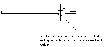
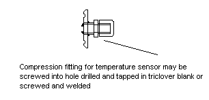
It is possible to use nominal ½” tri-clover connections in place of the screwed ¼” BSP fittings (NPT for the US market) and adapters made to allow the pitot tube and other components to be fitted and the test piece to be left in position permanently or else removed at will. This option is shown in Fig. 3 with typical dimensions shown for 1″ and 1 1/2″ pipe.
Fig. 4 shows a layout where tri-clover test connections are fitted in a permanently installed situation. Care should be taken to ensure that the use of such connections does not alter the essential geometry and location of the components used for the tests.
We supply sanitary test elbows in a variety of sizes with dimensions as Fig 3 above. See Test Elbow Specification for the full technical specification.
Fig. 5 shows the use of standard fittings adapted to suit the use of tri-clover connections:
Fig 5.1 Non-condensable gas test sample points
Pitot tube for Dryness Value and Superheat tests
Temperature sensor entry gland
The SQ1 Portable Steam Quality Test Kit is supplied with a Certificate of Conformity with EN 285, which describes the test components as being screwed. In the event that the test points or test point locations are modified, full compliance cannot be assured. Many problems with out of range test results are the consequence of using non standard test points or where the test methodology has been “improved”. Many companies use tri-clover connections and adapters without any problems. In the event that problems are experienced, a return to the standard layout as described in Figure 1 above should be the first step taken.
Non-condensable gas test point
The sample point should be on the top of the steam pipe and configured vertically upwards. Sufficient room is required above the socket to fit a ¼” isolating valve not supplied with the test kit). A ¼” BSP (NPT for US market) male compression fitting is provided with the test kit to allow the steam to condenser pipe to be fitted. The configuration should be identical to the drawing, that is to say a ¼” BSP (NPT for US market) female socket welded/silver soldered directly to the pipe. An equal tee may be used, but this may allow higher levels of gas to accumulate, with the tendency to produce worse results than achieved by using the standard method. When not in use, either a ¼” BSP NPT for US market) valve may be left in place, else a ¼” BSP (NPT for US market) plug fitted. If tri-clover connections are used, a blank tri-clover fitting may be used.Dryness Value and Superheat Test Point
These tests requires the pitot tube to be inserted into the flow of steam. It is important the pitot tube entry point is horizontal, level and parallel with the walls of the steam pipe, as any deviation towards the edge of the pipe can influence the results detrimentally.It is preferable that a swept bend is used and not a elbow or tee as this may result in undesirable turbulence at the sampling point. The pitot tube must sample against the flow of steam and not with it. That is to say the flow of steam should be into the pitot tube. A minimum 400 mm of straight pipe is required before the sample point, again to reduce the impact of turbulence on the sample. When not in use the sample point may be sealed with a ¼” BSP (NPT for US market) plug. If tri-clover connections are used, a blank tri-clover fitting may be used.


